Pyrolysis Reactors
Key Points
- There are a variety of reactor configurations for continuous feed fast pyrolysis.
- They vary primarily by solids handling, mixing, and heat transfer mechanism.
- Heat transfer and vapor removal are important to maximize liquid production and quality.
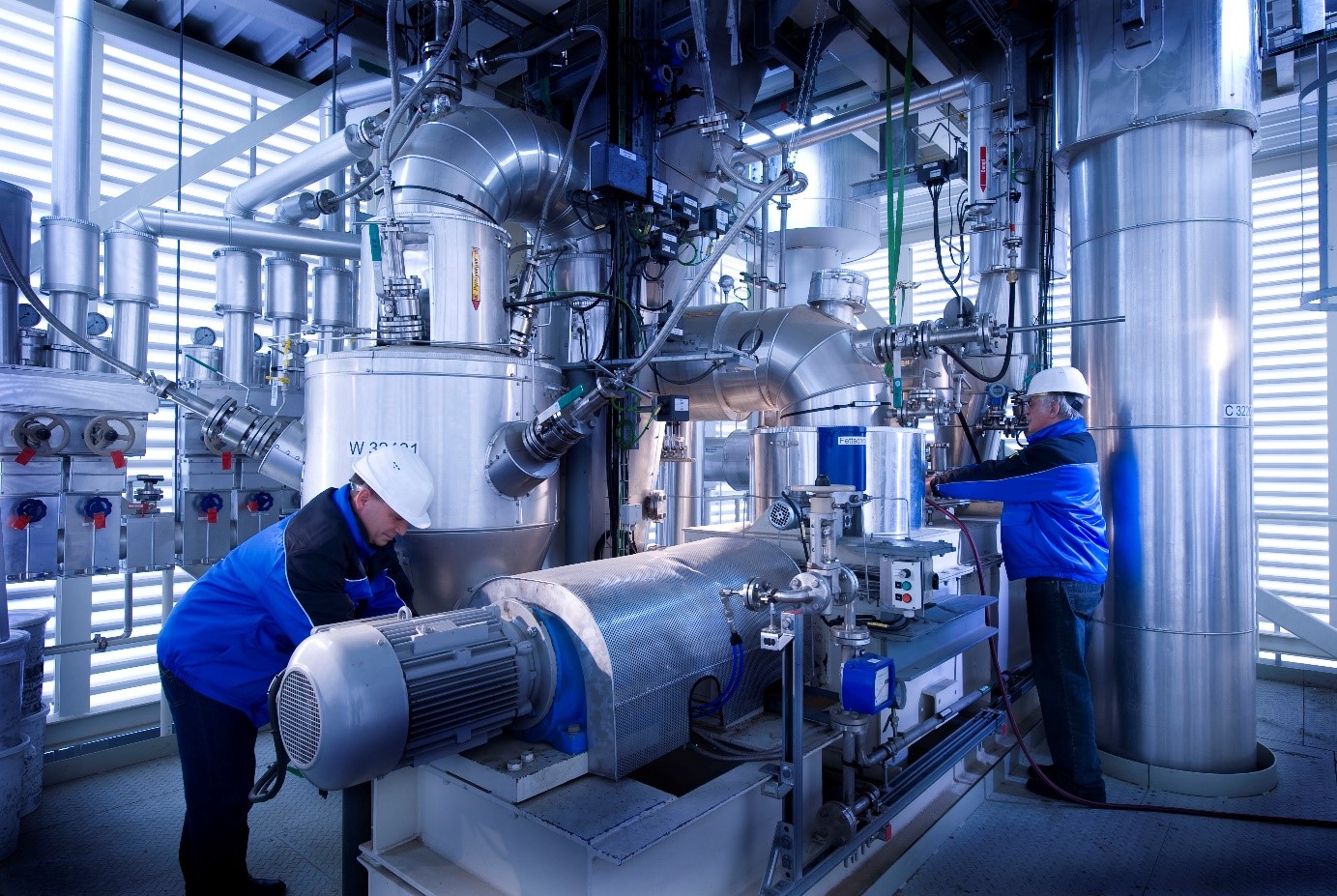
Example Applications:
- Empyro – Rotating Cone
- Fortum/Valmet – Circulating Fluid Bed
- Ensyn – Circulating Fluid Bed
- Bioliq – Auger/Screw
Function of fast pyrolysis reactors
The fundamental task of all fast pyrolysis reactors is to heat up the incoming biomass to the desired temperature and transport the solids with a specified residence time while maintaining inert conditions, i.e. avoiding leakage of air into the system. Fast pyrolysis reactors have the additional requirement to enable a very high heat transfer into the biomass particles while reducing vapour residence time inside the reactor to a minimum in order to maximize liquid yield. The biomass fed to the reactor is solid and it is generally challenging to realize high heat transfer into solid particles. Different designs have been proposed for fast pyrolysis reactors; many of them are based on the principle that the biomass particles are mixed with a preheated heat carrier, e.g. sand. Others realize high heat transfer by contact with a heated surface. The following sections align with these fundamental principles, starting with 1) fluidized beds, which apply a fluidization medium to mix a heat carrier with the biomass, 2) reactors, that apply mechanical agitation instead, and 3) so-called ablative pyrolysis reactors, that are based on intense contact between the biomass and a heated surface. The Table below provides an overview of the different reactor technologies.
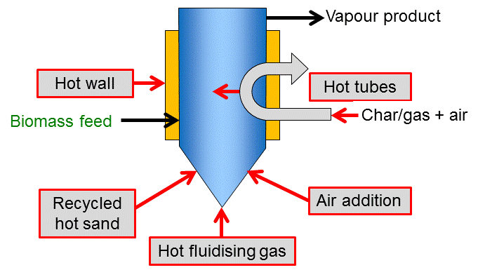
Apart from the challenge to enable high heat transfer into the biomass particle, this heat also needs to be supplied to the reactor vessel. Most reactor types apply one or a combination of the principles shown in the figure below. Direct heat exchange can be realized with a solid heat carrier or a hot gas stream (which is typically used for fluidization at the same time). The heat carrier or gas is often heated by combusting the solid char residue. Another efficient heat supply is partial combustion inside the reactor by controlled addition of air. These conditions do violate the textbook definition of pyrolysis as a process, but a comparable product distribution, i.e. direct thermochemical liquefaction, can be achieved. Indirect heat exchange can be performed via the reactor wall or tubes/ plates built into the reactor. Such heat exchangers can potentially be operated by different sources of heat (hot gas or liquids, electricity).
Fluidized beds
Fluidized beds have the advantages of being a well understood technology that is simple in construction and operation, allows for good temperature control and very efficient heat transfer to biomass particles due to intense mixing. They can be designed as bubbling fluidized beds which operate with a stationary fluidisation. In this configuration, only fine particles are entrained in the gas flow leaving the reactors. Another common approach is the circulating fluidized bed, in which heat carrier is recirculated in an external loop. The pyrolysis reactor is then placed in the riser and remaining char combusted in the fluidized bed in the presence of the heat carrier.
A typical configuration for bubbling fluidized bed pyrolysis is shown below with a representative product recovery section. Commercial plants may try to rely on a series of collection stages including de-misters although aerosol capture is notoriously difficult.
Bubbling fluid bed reactor
Heating can be achieved in a variety of ways as shown in Figure 1 and scaling is well understood. However, heat transfer to bed at large-scales of operation has to be considered carefully due to scale-up limitations of different methods of heat transfer. Depending on the method of heat transfer to the fluidized bed, the process can be built with (see Figure 2) or without (see Figure 5) heat carrier cycle.
Small biomass particle sizes of less than 2-3 mm are needed to achieve high biomass heating rates, and the rate of particle heating is usually the rate limiting step. Residence time of solids and vapours is controlled by the fluidising gas flow rate and is higher for char than for vapours. As char acts as an effective vapour cracking catalyst at fast pyrolysis reaction temperatures, rapid and effective char separation/elutriation is important. This is usually achieved by ejection and entrainment followed by separation in one or more cyclones so careful design of sand and biomass/char hydrodynamics is important.
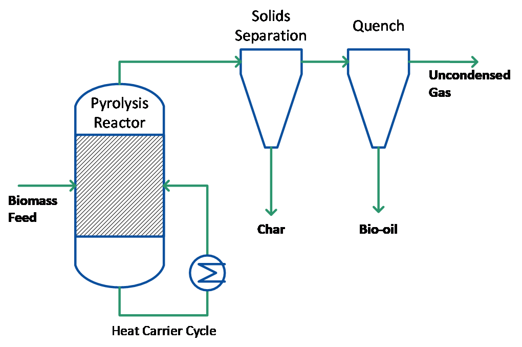
Figure 2: Pyrolysis process with separated heat carrier cycle and char/ vapour stream
Circulating fluid bed reactor
Circulating fluid bed (CFB) and transported bed reactor systems have many of the features of bubbling beds described above except that the residence time for the char is almost the same as for vapours and gas and char is more attrited due to the higher gas velocities which can lead to higher char contents in the collected bio-oil. An added advantage is that CFBs are suitable for very large throughputs even though the hydrodynamics are more complex – this technology is widely used at very high throughputs in the petroleum and petrochemical industry. Heat supply is usually from recirculation of heated sand from a secondary char combustor, which can be either a bubbling or circulating fluid bed (see Figure 3). In this respect the process is similar to a twin fluid bed gasifier except that the reactor (pyrolyser) temperature is much lower and the closely integrated char combustion in a second reactor requires careful control to ensure that the temperature and heat flux match the process and feed requirements. One of the unproven areas is heat transfer at large-scales of throughput.
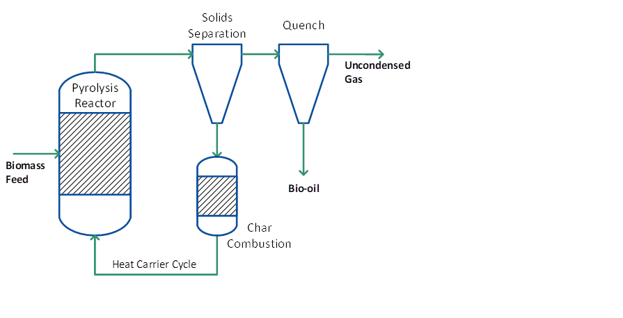
Figure 3: Pyrolysis process with combined heat carrier/ char cycle
Mechanical agitation
Biomass and a preheated heat carrier can also be mixed by mechanical means. This avoids the use of a fluidizing medium and the resulting gas/ vapour stream is undiluted.
Rotating cone reactor
In the rotating cone reactor biomass and heat carrier are intensively mixed by a mechanical device (rotating cone or any other mixer). Typically, a high sand-to-biomass ratio (10-30) is applied to provide sufficient heat and limit the temperature gradient over the reactor. The vapours are leaving the reactor at the top; sand and char are removed from the bottom and sent to the char combustor to reheat the sand. It follows that the principle process design is very similar to that of a circulating fluid bed reactor (see Figure 3). The vapours are fed to a quenching system to condense the bio-oil. Due to the application of mechanical mixing instead of gas mixing the non-condensable gases are undiluted and primarily consist of CO, CO2 and methane.
Auger reactor
Auger reactors that apply screws to move (and mix) biomass are a common choice for slow pyrolysis. They also can be designed and operated to achieve fast pyrolysis conditions. Similar to the rotating cone, this requires the addition of a preheated heat carrier to the biomass feed inside the reactor in an appropriate ratio. Mechanical mixing of biomass particles with the heat carrier by screws is not as intense as e.g. in fluidized beds, but the solid bed density is much higher so that comparably high heat transfer coefficients can be achieved. No fluidizing gas is needed, which eases the product recovery and gas cleaning section in a similar manner as for the rotating cone reactor. Moreover, only fine particles are entrained in the gas flow leaving the reactor so that pyrolysis char can be recovered separately, similar to the bubbling fluidized bed or ablative reactors (see Figure 2).
Naturally, a heat carrier loop is required to operate auger reactors for fast pyrolysis. Recirculation of the heat carrier can be achieved mechanically or by an (entrained flow) riser. Re-heating of the heat carrier is achieved by heat exchange, hot fluidizing gas in the riser, and/or combustion of entrained char particles during recirculation. The type of heat carrier used in the process will largely influence the combination of recirculation and re-heating method.

Figure 4: Auger reactor for fast pyrolysis of 0.5t/h wheat straw including cyclone and quench. Riser for the heat carrier sand to the right.
Ablative pyrolysis
Ablative pyrolysis is substantially different in concept compared to the other methods of fast pyrolysis. In all these other methods, the rate of reaction is limited by the rate of heat transfer through a biomass particle, which is why relatively small particles are required. The mode of reaction in ablative pyrolysis is analogous to melting butter in a frying pan, when the rate of melting can be significantly enhanced by pressing down and moving the butter over the heated pan surface. In ablative pyrolysis heat is transferred from the hot reactor wall to “melt” wood that is in contact with it under pressure. The pyrolysis front thus moves unidirectionally through the biomass particle. As the wood is moved away, the residual oil film both provides lubrication for successive biomass particles and also rapidly evaporates to give pyrolysis vapours for collection in the same way as other processes. The rate of reaction is strongly influenced by pressure onto the particle, the relative velocity of wood on the heat exchange surface and the reactor surface temperature. The key features of ablative pyrolysis are therefore as follows:
- High pressure of particle on hot reactor wall, achieved due to centrifugal force or mechanically;
- High relative motion between particle and reactor wall;
Mechanical pressure
When mechanical forces are used to press the biomass against the hot surface, as in the rotary and plate ablative pyrolysis reactors, reaction rates are not limited by heat transfer through the biomass particle. Large particles can therefore be used, and in principle there is no upper limit to the size that can be processed. The process in fact is limited by the rate of heat supply to the reactor rather than the rate of heat absorption by the pyrolysing biomass as in other reactors. No heat carrier cycle is needed and the process can be simplified as shown in Figure 5. Similar to mechanical mixing there is no requirement for inert gas, so the processing equipment is smaller, and the reaction system is thus more intensive. Ablative pyrolysis by mechanical pressure is surface area controlled so scaling is more costly and the reactor is mechanically driven, i.e. more complex in nature.
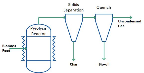
Figure 5: Pyrolysis process without heat carrier cycle.
Cyclone reactor
Another version of ablative pyrolysis reactor is the cyclone reactor. Here, carrier gas and particles enter the reactor tangentially and centrifugal forces press the particles against the hot reactor wall where they pyrolyse. The pressure against the hot wall is lower compared to when mechanical pressure is used, and the cyclone reactor therefore requires smaller particles. Furthermore, a carrier gas is necessary. No mechanically moving parts and no heat carrying medium (such as sand) are however needed in the ablative cyclone reactor system. The cyclone reactor also automatically separates the products, as solid residues leave the reactor at the bottom while gases and vapours leave at the top. The process can be designed in principle as shown in the Figure 5 except that there is no need for an additional solids separation because this takes place inside the reactor already.
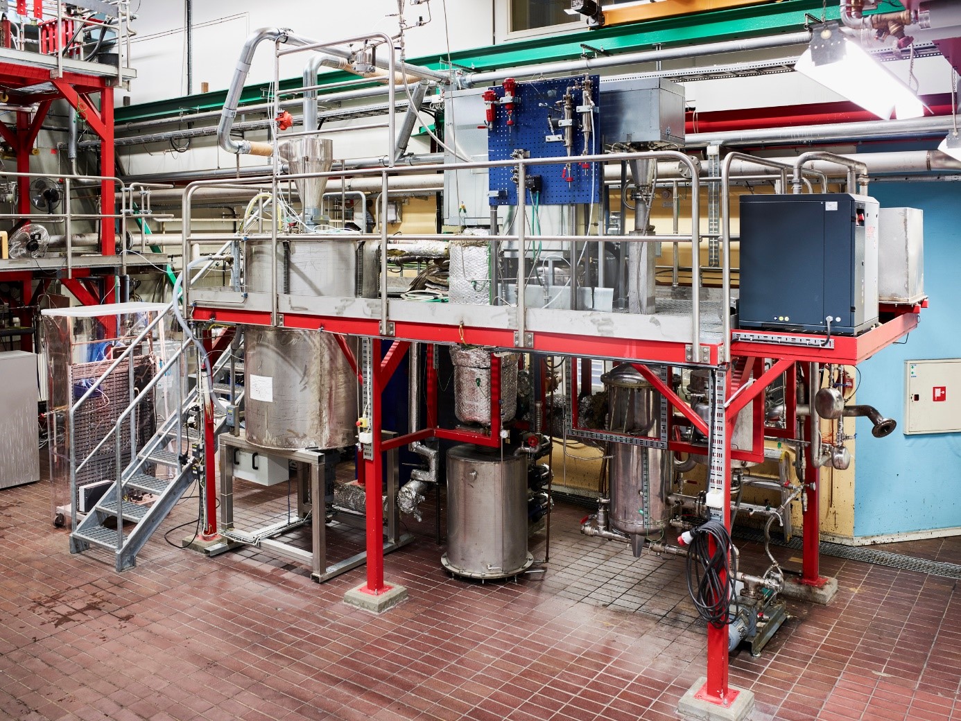
Figure 6. Cyclone pyrolysis pilot plant designed for about 30 kg biomass/h. Three large metal cylinders can be seen in the image, from the left: biomass hopper, solid residue container and container for condensed pyrolysis oil. The cyclone reactor is situated on top of the solid residue container.
Other Reactors
A variety of different reactor types have been tested successfully in laboratory scale to realise fast pyrolysis conditions. These include e.g. microwave, radiative, molten salt, and vacuum reactors. These technologies still await successful demonstration in pilot scale and are thus not covered in more detail here.

